logo
Supal (Changzhou) Precision Tools Co.,Ltd
हमारे बारे में
आपका पेशेवर एवं विश्वसनीय सहयोगी।
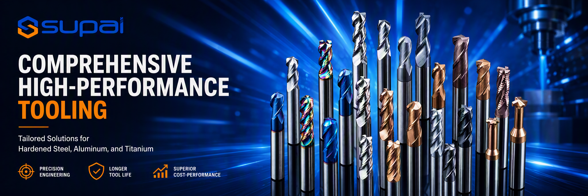
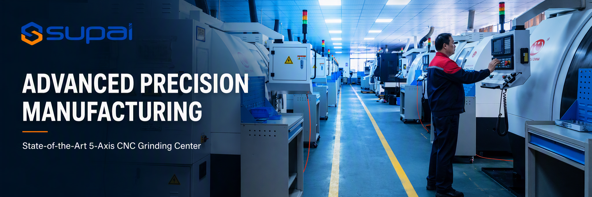
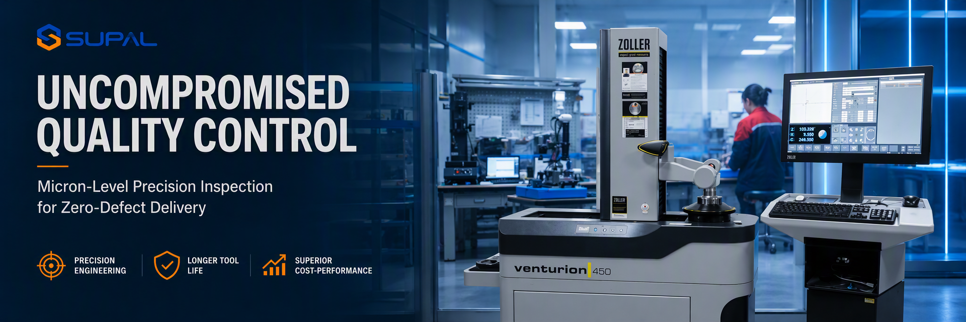
सुपाल (चांगझोउ) प्रिसिजन टूल्स कंपनी लिमिटेड कई वर्षों से ठोस कार्बाइड टूल्स के डिजाइन, उत्पादन और विपणन में लगी हुई है, जिसमें कुल निवेश 10 मिलियन से अधिक है, और इसमें अनुभवी कर्मचारियों का एक समूह शामिल है।एक पेशेवर टूल्स निर्माता के रूप में, यह चांगझोउ शियाशियाशु टूल्स एसोसिएशन के निदेशक सदस्यों में से एक बन गया है। कंपनी ने जर्मनी के वाल्टर और शट्टे, ऑस्ट्रेलिया के एएनसीए और पांच-अक्ष एनसी कटर ग्राइंडिंग मशीनें पेश की हैं; इसके अतिरिक्त, कंपनी ज़ोलर के कटर स्वचालित डिटेक्टर और यूरोटेक के पीज...
और जानें

0

स्थापित वर्ष:

0

दस लाख+
कर्मचारी

0

दस लाख+
वार्षिक बिक्री:
चीन Supal (Changzhou) Precision Tools Co.,Ltd उच्च गुणवत्ता
ट्रस्ट सील, क्रेडिट चेक, आरओएसएच और आपूर्तिकर्ता क्षमता मूल्यांकन। कंपनी के पास सख्ती से गुणवत्ता नियंत्रण प्रणाली और पेशेवर परीक्षण प्रयोगशाला है।
चीन Supal (Changzhou) Precision Tools Co.,Ltd विकास
आंतरिक पेशेवर डिजाइन टीम और उन्नत मशीनरी कार्यशाला। हम आपके लिए आवश्यक उत्पादों को विकसित करने के लिए सहयोग कर सकते हैं।
चीन Supal (Changzhou) Precision Tools Co.,Ltd विनिर्माण
उन्नत स्वचालित मशीनें, सख्ती से प्रक्रिया नियंत्रण प्रणाली हम आपकी मांग से परे सभी विद्युत टर्मिनलों का निर्माण कर सकते हैं।
चीन Supal (Changzhou) Precision Tools Co.,Ltd १००% सेवा
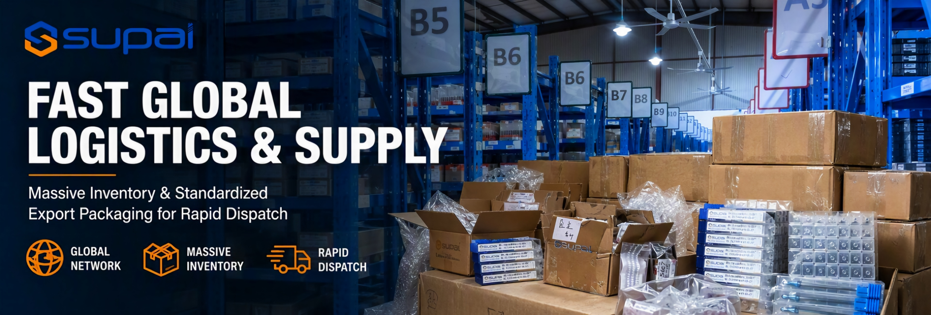
थोक और अनुकूलित छोटी पैकेजिंग, एफओबी, सीआईएफ, डीडीयू और डीडीपी। हम आपकी चिंताओं का सबसे अच्छा समाधान खोजने में आपकी सहायता करेंगे।

गुणवत्ता कार्बाइड मिलिंग उपकरण & वर्ग अंत मिलें निर्माता

ऐसे उत्पाद खोजें जो आपकी आवश्यकताओं को बेहतर ढंग से पूरा करते हों।
मामले और समाचार
नवीनतम हॉट स्पॉट।
Carbide End Mill Chipping vs. Normal Wear: A Practical Failure-Diagnosis Guide
Carbide End Mill Chipping vs. Normal Wear: A Practical Failure-Diagnosis Guide A carbide end mill is a consumable tool, but not every damaged edge represents normal wear. Uniform flank wear is a predictable result of cutting. Chipping, micro-fracture, corner breakage, and sudden tool failure indicate that the edge has been exposed to mechanical or thermal loads beyond what the tool and setup can tolerate. The difference matters. If normal wear is mistaken for chipping, a shop may reduce parameters unnecessarily and lose productivity. If chipping is treated as normal wear, the process may continue until the tool breaks, the part is scrapped, or the spindle and workholding are exposed to a severe load. A reliable diagnosis begins with the location and pattern of the damage. Engineers should examine which flute is affected, where the damage starts, whether all edges show the same wear, and what changed in the sound, spindle load, chips, surface finish, and dimensions before the failure. This guide presents a practical method for distinguishing normal carbide wear from mechanical chipping and for connecting each pattern to likely causes in the tool, holder, machine, toolpath, coolant strategy, and cutting parameters. What Normal End-Mill Wear Looks Like Normal wear generally develops gradually and relatively consistently across the cutting edges that share the load. Under magnification, the flank behind the cutting edge may show a narrow worn land. The cutting edge becomes less sharp, cutting forces rise slowly, and the surface finish or dimensional accuracy changes in a repeatable direction. Typical indicators include: A continuous wear band along the engaged cutting length Similar wear on all flutes when runout is controlled Gradual rather than sudden increase in spindle load Predictable reduction in surface quality Stable chips with no evidence of severe impact or packing Dimensional drift that progresses over multiple parts Coating wear concentrated in the active cutting zone Normal wear does not mean the tool should be used until it fails. A process should define a replacement point based on dimensional control, surface finish, edge condition, spindle load, or a proven number of parts. The objective is to replace the tool during predictable wear, before the edge loses enough strength to begin chipping. How Mechanical Chipping Differs Chipping removes small or large fragments from the cutting edge. The fracture can be limited to the corner, appear as micro-notches along the flute, or propagate into a major break. Unlike uniform flank wear, chipping is often irregular. Common signs include: One flute is damaged more severely than the others The corner breaks while the remaining cutting length appears relatively sharp Small notches appear near the depth-of-cut line The cutting edge has a jagged profile rather than a smooth wear land Cutting sound changes suddenly Spindle load shows intermittent peaks The finished surface contains random gouges, steps, or repeating marks from the damaged flute Tool life varies widely between nominally identical setups Chipping is usually associated with impact, uneven loading, insufficient edge support, vibration, chip recutting, interrupted cutting, excessive deflection, or thermal shock. Several causes may occur together. Read the Damage Location Before Changing Parameters Chipping on one flute only When one flute fails before the others, check runout and clamping first. A tool with radial runout does not divide the chip load evenly. The high flute removes a larger chip, while the other flutes may rub. This combination increases force, heat, and edge stress. Clean the holder, collet, nut, tool shank, and spindle interface according to the shop's maintenance procedure. Measure runout close to the cutting edge, not only at the shank. Inspect the collet and holder for wear, contamination, or damage. Replacing the end mill without correcting the source can reproduce the same failure. Corner chipping The corner of a square end mill is a stress concentration. It is exposed to radial and axial forces simultaneously and can be vulnerable during entry, exit, sharp direction changes, and heavy engagement. If the part design permits, a corner-radius geometry can provide more edge support than a sharp square corner. Supal's corner radius end mills provide options for processes where corner strength and stable edge life are more important than producing a perfectly sharp internal corner. Corner chipping can also indicate excessive radial engagement, an aggressive entry, inadequate finishing allowance, or a toolpath that drives the cutter into a corner with a sudden increase in engagement. Notching at the depth-of-cut line A localized notch where the cutting edge repeatedly enters the workpiece can result from a concentrated mechanical and thermal load. Scale, a hardened surface layer, work hardening, interrupted material, or repeated cutting at one axial position may contribute. Changing axial depth can distribute wear over a different section of the flute, but this should be evaluated together with workpiece condition, coating, edge preparation, coolant, and toolpath. Simply moving the wear line does not correct an unsuitable tool or unstable process. Chipping along several flutes Damage across multiple flutes points toward a system-level problem: chatter, chip recutting, excessive engagement, an edge that is too weak for the operation, or unsuitable cutting data. Inspect the cavity for trapped chips and compare the damage pattern with the surface marks. Random edge damage and random scratches often indicate recutting, while regular waves suggest vibration. Complete fracture near the flute or neck A major fracture may follow a severe overload, collision, excessive tool projection, weak cross-section, or accumulated micro-cracks. Small-diameter tools are particularly sensitive to runout, handling, holder quality, and sudden engagement changes. Review the program, holder, tool reach, and actual feature clearance before blaming carbide quality. For applications using very small diameters, review Supal's micro end mills and define the setup around minimum runout, short projection, controlled entry, and reliable chip removal. Separate Chipping from Chatter Chatter is self-excited vibration within the tool-machine-workpiece system. It can cause edge chipping, but not every chipped tool is the result of chatter. Evidence of chatter may include: Repeating waves or evenly spaced marks on the workpiece A strong tonal sound rather than random impacts Damage at similar positions around multiple flutes Instability that changes when spindle speed is adjusted Increased sensitivity with longer tool projection or weaker workholding First reduce unnecessary overhang and confirm workpiece clamping. Check holder condition and runout. Review radial engagement, axial engagement, and entry conditions. A variable-pitch or variable-helix tool may help disrupt periodic forces, but geometry cannot compensate for a loose fixture, excessive reach, or a holder with unacceptable runout. Avoid changing multiple parameters at once. A controlled spindle-speed adjustment can help identify a stability issue, while a feed reduction alone may create rubbing and heat without eliminating the vibration source. Tool Geometry and Substrate Must Match the Failure Mode A harder tool is not automatically a tougher tool. Carbide grade, grain structure, cobalt content, edge preparation, core diameter, helix, rake, flute count, coating, and corner design all influence the balance between wear resistance and fracture resistance. A sharp edge reduces cutting force but has less material supporting it. A honed or protected edge can resist impact but may increase force in an operation that needs very low cutting pressure. More flutes can increase potential feed capacity but reduce chip space. A thicker core improves rigidity but also changes flute volume. If a standard tool repeatedly fails because the reach, neck, flute length, or corner geometry is unsuitable, a custom milling tool may allow the geometry to be balanced around the actual feature rather than forcing a generic tool into the application. A Controlled Troubleshooting Sequence When chipping occurs, document the failed tool before discarding it. Mark the flute numbers, photograph the edge under consistent magnification, and record the part count, spindle load, sound, surface condition, and program location. Then troubleshoot in this order: Confirm there was no collision or programming error. Check rapid moves, entry, retract, stock condition, fixture clearance, and unexpected remaining material. Inspect runout and the holder system. Clean interfaces, measure near the cutting edge, and compare damage among flutes. Reduce tool projection. Use the shortest practical overhang and cutting length. Verify workholding. Check part support, fixture rigidity, and whether thin walls are moving during the cut. Examine chip evacuation. Look for packed or recut chips, especially in slots and deep pockets. Review engagement changes. Identify corners, entries, exits, and interrupted regions where load rises suddenly. Review tool geometry. Check whether flute count, corner design, edge preparation, coating, and reach match the operation. Review cutting data. Use the supplier's range as a starting reference and adjust one variable at a time. Run a controlled comparison. Keep material, holder, tool projection, and toolpath constant while evaluating the selected change. The final parameters must be validated on the specific machine, holder, fixture, workpiece grade, and coolant system. A numerical setting copied from another machine should not be treated as a guaranteed solution. Parameter Adjustments by Symptom Chipping during entry Check whether the end mill supports the programmed plunge or ramp. Reduce sudden engagement, use a suitable ramp or helical entry, or predrill when appropriate. Verify that the tool is center-cutting if the program requires it. Chipping in internal corners The engagement angle increases sharply in corners. Use a toolpath that controls engagement, reduce leftover stock in the corner, and avoid abrupt direction changes. A smaller radial engagement with a consistent path may be more stable than a conventional full-width turn. Chipping after a long stable cut Look for accumulated heat, progressive wear, coating loss, chip packing, and a wear limit that has been exceeded. The tool may begin in normal wear and then lose enough edge strength to fracture. Establishing an earlier replacement point can be more effective than reducing the entire process. Chipping with built-up edge Adhered material can repeatedly break away and pull at the carbide edge. Review workpiece-specific geometry, coating or flute polish, lubrication, chip thickness, and coolant direction. Correct the adhesion mechanism rather than only lowering feed. Chipping with long tool reach Reduce projection wherever possible, use a necked tool designed for the feature, strengthen workholding, and apply a toolpath with controlled radial engagement. Lowering cutting force can help, but excessive reach remains a structural limitation. Common Diagnostic Mistakes Blaming the carbide grade first Material quality matters, but runout, holder contamination, toolpath overload, and chip recutting are more common process variables. Verify the system before changing the substrate. Reducing feed without checking chip thickness A feed that is too low can cause rubbing, heat, and unstable edge loading. Any adjustment must remain within a practical cutting range for the exact tool and material. Inspecting only the broken tool The workpiece surface, chip shape, holder, collet, fixture, spindle-load record, and program location contain essential evidence. Tool damage alone rarely proves the root cause. Changing tool, coating, speed, feed, and coolant together Multiple simultaneous changes can produce a better result without revealing why. Change one controlled factor at a time whenever production conditions permit. Treating all edge loss as the same failure Corner chipping, depth-of-cut notching, single-flute overload, multi-flute micro-chipping, and complete neck fracture point to different mechanisms. Record the exact location and pattern. Frequently Asked Questions Is a chipped carbide end mill always caused by excessive feed? No. Excessive chip load can cause overload, but chipping may also result from runout, chatter, chip recutting, long overhang, weak workholding, sudden engagement, unsuitable geometry, adhesion, or thermal effects. How can I tell whether runout is causing the failure? Compare the flutes. If one flute carries most of the wear or chipping while the others remain relatively sharp, uneven loading is likely. Clean and inspect the holder system and measure runout near the cutting edge. Will a corner-radius end mill last longer than a square end mill? It often provides stronger corner support when the part design allows a radius. Actual life still depends on engagement, material, coating, holder, runout, toolpath, and cutting parameters. Why do micro end mills break without visible wear? Small tools have limited cross-section and are highly sensitive to runout, handling damage, projection, chip packing, and sudden load changes. Failure can occur before a large wear land becomes visible. What information should be sent to the tool supplier? Provide the workpiece grade and hardness, operation, feature dimensions, tool diameter and reach, holder type, runout measurement, coolant method, cutting data, toolpath description, part count, and clear photographs of every flute and the machined surface. Conclusion Normal wear develops gradually and can be managed through a defined replacement limit. Chipping is an irregular fracture process that signals unstable or excessive loading. The most efficient diagnosis begins with the pattern: which flute failed, where the damage started, and what the machine, chips, and workpiece showed at the same time. Before changing the carbide grade or reducing productivity, verify runout, tool projection, workholding, chip evacuation, engagement changes, and tool geometry. Then adjust one parameter at a time and confirm the result on the actual machine. Supal (Changzhou) Precision Tools Co., Ltd. supplies carbide end mills and customized cutting solutions for precision machining. To review an edge-failure problem, contact Supal with tool photos, workpiece material, holder and runout information, feature dimensions, current parameters, coolant method, and the exact point in the toolpath where damage occurs. This evidence helps identify a practical tool and process direction for controlled on-machine validation.

2026

07/29

एल्यूमीनियम के लिए अनकोटेड बनाम डीएलसी एंड मिलः चिप वेल्डिंग और खराब सतह खत्म करने से कैसे बचें
एल्यूमीनियम को आमतौर पर मशीनीकृत करना आसान माना जाता है, लेकिन स्थिर एल्यूमीनियम मिलिंग केवल धुरी को तेजी से चलाने की बात नहीं है। उत्पादन में सबसे आम समस्याएं अक्सर चिप वेल्डिंग होती हैं,निर्मित किनारा, चिप्स का पुनः काटना, बर्न गठन, अस्थिर आयाम, और एक धुंधली या खरोंच वाली सतह। ये विफलताएं निकटता से जुड़ी हुई हैंः जब चिप्स साफ नहीं होते हैं, तो काटने वाले क्षेत्र को साफ नहीं किया जाता है।एल्यूमीनियम काटने के किनारे के लिए चिपके हुए, प्रभावी उपकरण ज्यामिति को बदलता है, काटने की ताकत को बढ़ाता है, और तैयार सतह को नुकसान पहुंचाता है। इसलिए एक गैर-लेपित पॉलिश कार्बाइड एंड मिल और एक डीएलसी लेपित उपकरण के बीच चयन एक कॉस्मेटिक निर्णय नहीं है। सही विकल्प एल्यूमीनियम ग्रेड, सिलिकॉन सामग्री, ऑपरेशन प्रकार पर निर्भर करता है,शीतलक रणनीति, धुरी क्षमता, उपकरण व्यास, और आवश्यक सतह की गुणवत्ता। उपकरण ज्यामिति और प्रक्रिया स्थिरता कोटिंग के रूप में महत्वपूर्ण हैं। यह मार्गदर्शिका बताती है कि सीएनसी मशीनिस्ट, प्रक्रिया इंजीनियर,और खरीद टीमों एक सार्वभौमिक काटने पैरामीटर पर भरोसा किए बिना एक उपयुक्त एल्यूमीनियम अंत मिल का चयन और एक विश्वसनीय प्रारंभ प्रक्रिया का निर्माण कर सकते हैं. एल्यूमीनियम किनारे पर क्यों टिकता है जब काम करने वाले टुकड़े की सामग्री दबाव और घर्षण के तहत रेक चेहरे और काटने के किनारे पर चिपके हुए हों तो बढ़ी हुई किनारें बनती हैं।एल्यूमीनियम विशेष रूप से आसंजन के लिए प्रवण है क्योंकि कई ग्रेड लचीले होते हैं और छोटे चिप्स में टूटने के बजाय चिपकने की प्रवृत्ति होती है. एक बार जमा होने के बाद, काटने का किनारा अब अपने डिज़ाइन किए गए रेक कोण के साथ काम नहीं कर रहा है। जमा बार-बार बढ़ता है और टूट जाता है। इसका एक हिस्सा वर्कपीस पर वेल्ड हो सकता है,जबकि एक और भाग काटने के किनारे से छोटे टुकड़े हटा सकते हैं. तत्काल लक्षणों में अक्सर शामिल हैंः एक उज्ज्वल, समान खत्म के बजाय एक असमान या फटी सतह फ्लूट्स में पैक एल्यूमीनियम चक्र के दौरान धुरी भार या काटने के शोर में वृद्धि भाग के ऊपरी या निचले किनारे पर बर्स प्रभावी उपकरण व्यास में परिवर्तन के रूप में आयामी बहाव पुनः कट चिप्स के कारण आकस्मिक खरोंच समय से पहले किनारे की क्षति जो घर्षण के पहनने से संबंधित नहीं है जड़ कारण हमेशा अपर्याप्त स्नेहन नहीं है. बहुत अधिक फ्लू के साथ एक उपकरण, अपर्याप्त चिप स्थान, एक असभ्य फ्लू सतह, अत्यधिक runout,या एक अनुपयुक्त उपकरण पथ एक ही विफलता पैदा कर सकते हैं, यहां तक कि जब शीतलक मौजूद है. अनकोटेड पॉलिश कार्बाइडः अक्सर सबसे अच्छा शुरुआती बिंदु कई फोर्ज किए गए एल्यूमीनियम मिश्र धातुओं के लिए, अत्यधिक पॉलिश किए गए फ्लूट्स के साथ एक तेज गैर-कोटेड कार्बाइड अंत मिल एक प्रभावी पहली पसंद है।एक पारंपरिक उच्च घर्षण कोटिंग की अनुपस्थिति एक तेज काटने के किनारे को संरक्षित करती है, जबकि पॉलिश रेक और फ्लूट सतहें नरम एल्यूमीनियम की चिपकने की प्रवृत्ति को कम करती हैं। जब एक अनकोटेड उपकरण उपयुक्त है एक गैर लेपित पॉलिश अंत मिल आमतौर पर मूल्यांकन के लायक है जबः सामग्री अपेक्षाकृत नरम या सामान्य प्रयोजन के एल्यूमीनियम मिश्र धातु है आवेदन के लिए एक बहुत तेज धार और कम काटने के दबाव की आवश्यकता है मशीन प्रभावी बाढ़ शीतल, न्यूनतम मात्रा स्नेहन, या हवा सहायता चिप निकासी है ऑपरेशन परिष्करण, प्रोफाइलिंग, पॉकेटिंग, या सामान्य स्लॉटिंग पर्याप्त चिप स्थान के साथ है प्राथमिकता अधिकतम घर्षण प्रतिरोध के बजाय एक उज्ज्वल सतह और साफ किनारे है एल्यूमीनियम के लिए दो या तीन बांसुरी वाला डिज़ाइन आम है क्योंकि यह एक ही व्यास के चार बांसुरी वाले उपकरण की तुलना में अधिक बांसुरी की मात्रा प्रदान करता है।अधिक चिप स्थान स्लॉटिंग और गहरी जेब मशीनिंग के दौरान पैकिंग को रोकने में मदद करता हैएक उच्च हेलिक्स और सकारात्मक रेक काटने की शक्ति को कम कर सकता है और कतरनी क्रिया में सुधार कर सकता है, लेकिन अंतिम ज्यामिति को अभी भी उपकरण व्यास और ओवरहेंज के लिए पर्याप्त कोर शक्ति प्रदान करनी चाहिए। सुपल की खोज करें उपलब्ध हैएल्यूमीनियम के लिए अंत मिलजब फ्लूट की संख्या, काटने की लंबाई और अनुप्रयोग-विशिष्ट ज्यामिति की तुलना की जाती है। जब डीएलसी कोटिंग मूल्य जोड़ती है डीएलसी, या हीरे जैसा कार्बन, गैर लौह मशीनिंग में अपने कम घर्षण, विरोधी आसंजन व्यवहार के लिए मूल्यवान है।यह एल्यूमीनियम और उपकरण के बीच सामग्री हस्तांतरण को कम कर सकते हैंयह विशेष रूप से उपयोगी है जब एक गैर-कोटेड उपकरण सही चिप निकासी और स्नेहन के बावजूद बार-बार आसंजन का अनुभव करता है। ऐसे अनुप्रयोग जिन्हें डीएलसी से लाभ हो सकता है एक डीएलसी-लेपित एल्यूमीनियम अंत मिल पर विचार किया जा सकता है जबः ऑपरेशन लंबे समय तक चलता है और किनारे की सफाई बनाए रखना मुश्किल है एल्यूमीनियम ग्रेड घर्षण या पहनने में तेजी लाने वाले घटकों को शामिल है स्नेहन सीमित है लेकिन काटने का तापमान नियंत्रित रहता है लंबे उत्पादन बैच में सतह की गुणवत्ता स्थिर होनी चाहिए सूक्ष्म औजारों या छोटे व्यास के औजारों को कम घर्षण और स्थिर चिप प्रवाह की आवश्यकता होती है एक सिद्ध uncoated ज्यामिति अच्छी तरह से काम करता है, लेकिन प्रक्रिया आसंजन और पहनने के लिए अतिरिक्त प्रतिरोध की जरूरत है डीएलसी को सही ज्यामिति के विकल्प के रूप में नहीं माना जाना चाहिए। अपर्याप्त फ्लूट स्थान या एक गूंगे किनारे के साथ एक लेपित उपकरण अभी भी चिप्स पैक कर सकता है। कोटिंग मोटाई और किनारे की तैयारी भी मायने रखती हैःयदि कोटिंग एक काटने के किनारे को गोल करती है जो बेहद तेज रहना चाहिए, काटने के दबाव में वृद्धि हो सकती है और स्मेकिंग को बढ़ावा दे सकती है। एक डीएलसी उपकरण को मानकीकृत करने से पहले, एक ही नियंत्रित परिस्थितियों में एक गैर-कोटेड पॉलिश उपकरण के साथ इसकी तुलना करें। धुरी भार, किनारे निर्माण, सतह खत्म, burr गठन की निगरानी,और स्थिर भागों की संख्या के बजाय केवल उपस्थिति से प्रदर्शन का न्याय. कोटिंग नाम से ज़्यादा ज़रूरी है औजारों की ज्यामिति खरीद विनिर्देशों में अक्सर "अनकोटेड" या "डीएलसी" पर ध्यान केंद्रित किया जाता है, लेकिन फ्लूट ज्यामिति निर्धारित करती है कि चिप कैसे बनाई जाती है और परिवहन किया जाता है। फ्लूट की संख्या और चिप क्षमता पूर्ण-चौड़ाई वाले स्लॉटिंग, गहरी जेब, या गमी एल्यूमीनियम के लिए, चिप स्थान को प्राथमिकता दें। कम फ्लूट की संख्या आम तौर पर बड़े गलेट और निकासी के लिए अधिक जगह प्रदान करती है।कठोर मशीनों पर हल्के रेडियल फिनिशिंग के लिए, एक अतिरिक्त बांसुरी उत्पादकता में सुधार कर सकती है, बशर्ते कि चिप्स अभी भी कटौती छोड़ सकें। रेक कोण और किनारे की तीक्ष्णता एक सकारात्मक रेक और तेज काटने का किनारा एल्यूमीनियम को धक्का देने और चिपकाए जाने के बजाय काटने में मदद करता है।पर्याप्त समर्थन के बिना अत्यधिक तीक्ष्णता एक छोटे उपकरण को हैंडलिंग क्षति के लिए कमजोर बना सकती हैसही संतुलन व्यास और संचालन पर निर्भर करता है। हेलिक्स और फ्लूट पॉलिशिंग एक उच्च हेलिक्स चिकनी काटने और ऊपर की ओर चिप प्रवाह का समर्थन कर सकते हैं, जबकि एक पॉलिश फ्लूट घर्षण और सामग्री आसंजन को कम करता है। गहरे गुहाओं में, उपकरण पहुंच, फ्लूट की लंबाई,और गर्दन के रिक्त स्थान पर भी विचार किया जाना चाहिएसबसे छोटा व्यावहारिक ओवरहॉन्ग सामान्यतः सबसे स्थिर परिणाम प्रदान करता है। कोने का डिजाइन तेज चौकोर कोने तब उपयोगी होते हैं जब भाग को इसकी आवश्यकता होती है, लेकिन यह उपकरण के सबसे कमजोर बिंदु पर तनाव को केंद्रित करता है।एक छोटे कोण त्रिज्या किनारे को मजबूत और स्थिरता में सुधार कर सकते हैं जब घटक डिजाइन यह अनुमति देता हैयह विशेष रूप से कच्चे और उच्च संलग्नता वाले संचालन में प्रासंगिक है। एल्यूमीनियम विशिष्ट उपकरण से परे व्यापक ज्यामिति विकल्पों के लिए, समीक्षा Supal केकार्बाइड मिलिंग टूल्स. एक व्यावहारिक पैरामीटर-समायोजन रणनीति काटने के आंकड़ों को एक नियंत्रित प्रारंभिक बिंदु के रूप में माना जाना चाहिए, न कि सार्वभौमिक गारंटी के रूप में। हमेशा सटीक एल्यूमीनियम ग्रेड, उपकरण व्यास, फ्लूट की संख्या, उपयोगी काटने की लंबाई, धारक की स्थिति की पुष्टि करें,स्पिंडल सीमा, मशीन की कठोरता, शीतलक वितरण, और रेडियल/अक्षीय जुड़ाव। बुनियादी संबंध हैंः धुरी गति काटने की गति और उपकरण व्यास पर निर्भर करती है। टेबल फ़ीड स्पिनडल स्पीड, फ्लूट की संख्या और प्रति दांत फ़ीड पर निर्भर करता है। जब रेडियल एंगेजमेंट छोटा हो जाता है तो चिप की मोटाई बदल जाती है, इसलिए प्रोग्राम किए गए फीड के लिए क्षतिपूर्ति की आवश्यकता हो सकती है। प्रारंभिक संदर्भ के रूप में उपकरण आपूर्तिकर्ता की अनुशंसित सीमा का उपयोग करें, फिर एक समय में एक चर को समायोजित करें। यदि एल्यूमीनियम उपकरण के लिए वेल्डिंग है पुष्टि करें कि उपकरण एल्यूमीनियम के लिए डिज़ाइन किया गया है और इसमें पॉलिश, खुले फ्लोट हैं। वास्तविक काटने के क्षेत्र में शीतलक, एमक्यूएल, या हवा वितरण की जाँच करें। यह सुनिश्चित करें कि प्रति दाँत भोजन इतना कम न हो कि किनारा काटने के बजाय रगड़ता हो। अनावश्यक रेडियल एंगेजमेंट को कम करें या गर्मी एकाग्रता को सीमित करने के लिए एक अनुकूलन उपकरण पथ का उपयोग करें। निकासी और धारक की स्वच्छता की जाँच करें। एक डीएलसी विकल्प की तुलना केवल ज्यामिति और चिप निकासी नियंत्रण में होने के बाद करें। यदि चिप्स फिर से काट रहे हैं हवा या शीतल द्रव की दिशा में सुधार करें न कि केवल कटौती से दूर वॉल्यूम बढ़ाएं। यदि चिप स्थान अपर्याप्त है तो फ्लूट की संख्या कम करें। उपकरण को गहरे छेद में बिना किसी स्पष्ट निकासी मार्ग के दफनाने से बचें। यदि आवश्यक हो तो कठोर प्रत्यक्ष डुबकी के बजाय रैंपिंग या हेलिकल प्रवेश का प्रयोग करें। गहरी जेब में कदम-नीचे की रणनीति और उपकरण पथ दिशा पर विचार करें। यदि सतह खत्म खराब है सबसे पहले यह निर्धारित करें कि निशान आवधिक हैं या यादृच्छिक। आवधिक निशान रूनआउट, चैटर, स्पिंडल या धारक मुद्दों, या अस्थिर परिष्करण भत्ता का संकेत दे सकते हैं।यादृच्छिक खरोंच अधिक बार तैयार सतह को पार करने वाले ढीले चिप्स का सुझाव देते हैं. खत्म करने के लिए, एक सुसंगत अनुदान छोड़ दें, एक स्थिर उपकरण संलग्नक का उपयोग करें, ओवरहैंग को कम से कम करें, और अंतिम पास के लिए क्षतिग्रस्त कठोर किनारे का उपयोग करने से बचें।एक विशेष परिष्करण उपकरण उच्च मूल्य वाले घटकों में प्रक्रिया नियंत्रण को आसान बना सकता है. एल्यूमीनियम मिलिंग में आम गलतियाँ प्रत्येक ऑपरेशन के लिए एक सामान्य प्रयोजन लेपित चार-फ्लोट उपकरण का उपयोग करना सामान्य प्रयोजन के उपकरण हल्के कटौती में काम कर सकते हैं, लेकिन सीमित चिप स्थान और कम उपयुक्त सतह स्लॉट और गहरी जेब में पैकिंग का कारण बन सकती है। जब भी कट अस्थिर लगता है फ़ीड को कम करना कारण का निदान किए बिना फ़ीड को कम करने से प्रक्रिया को रगड़ने, गर्मी और आसंजन को बढ़ाने में धक्का हो सकता है।और एक बड़ी फ़ीड कमी करने से पहले धुरी गति. अधिक शीतल द्रव स्वचालित रूप से चिप वेल्डिंग हल करता है मानते हुए शीतलक को काटने के किनारे तक पहुंचना चाहिए और चिप्स को दूर ले जाने में मदद करनी चाहिए। खराब रूप से लक्षित प्रवाह से चिप्स के पुनर्चक्रण से भरी गहरी जेब रह सकती है। आधार ज्यामिति की पुष्टि किए बिना डीएलसी का चयन करना कम घर्षण उपयोगी है, लेकिन यह अनुपयुक्त बांसुरी की संख्या, अपर्याप्त ग्लूटेट वॉल्यूम, अत्यधिक प्रवाह, या कमजोर कार्य पकड़ की भरपाई नहीं कर सकता है। एक अलग उपकरण व्यास या मशीन से मानकों की नकल एक ही सतह की गति और फ़ीड अवधारणा एक बहुत ही अलग परिणाम पैदा कर सकते हैं जब व्यास, धुरी क्षमता, उपकरण प्रक्षेपण, या मशीन गतिशीलता परिवर्तन। पुनः गणना और प्रक्रिया मान्य। इंजीनियरों और खरीदारों के लिए उपकरण चयन चेकलिस्ट उद्धरण का अनुरोध करने या उत्पादन उपकरण को मंजूरी देने से पहले, दस्तावेजः सटीक एल्यूमीनियम ग्रेड और स्थिति ऑपरेशन: स्लॉटिंग, पॉकेटिंग, साइड फ्रिलिंग, फिनिशिंग, ड्रिलिंग या चैंफरिंग उपकरण व्यास, काटने की लंबाई, पहुंच और शाफ्ट की आवश्यकताएं रेडियल और अक्षीय जुड़ाव मशीन के धुरी की गति और धारक प्रकार शीतलक, एमक्यूएल या वायु-विस्फोट क्षमता आवश्यक सतह खत्म, burr स्थिति, और आयामी सहिष्णुता वर्तमान विफलता मोड और उपयोग किए गए काटने के किनारे की तस्वीरें बैच का आकार और क्या उपकरण कच्चे या परिष्करण के लिए समर्पित किया जाएगा यह जानकारी आपूर्तिकर्ता को केवल भाग सामग्री के बजाय प्रक्रिया के आधार पर ज्यामिति और कोटिंग की सिफारिश करने की अनुमति देती है। अक्सर पूछे जाने वाले प्रश्न क्या एल्यूमीनियम के लिए एक अनकोटेड एंड मिल से डीएलसी हमेशा बेहतर होता है? नहीं. एक तेज, पॉलिश अनकोटेड उपकरण अक्सर कई एल्यूमीनियम संचालन के लिए एक उत्कृष्ट विकल्प है। डीएलसी मूल्यवान हो जाता है जब प्रक्रिया को अतिरिक्त विरोधी आसंजन व्यवहार या पहनने के प्रतिरोध की आवश्यकता होती है,लेकिन इसका प्रदर्शन अभी भी ज्यामिति पर निर्भर करता है, किनारे की स्थिति, और तापमान नियंत्रण। एक एल्यूमीनियम के अंत की मिल में कितने बांसुरी होने चाहिए? दो या तीन फ्लूट आम हैं क्योंकि वे उदार चिप स्थान प्रदान करते हैं। सबसे अच्छा विकल्प इस बात पर निर्भर करता है कि क्या ऑपरेशन पूर्ण स्लॉटिंग, पॉकेटिंग, रूफिंग या लाइट रेडियल फिनिशिंग है।फ्लूट की संख्या में वृद्धि न करें जब तक कि निकासी विश्वसनीय बनी हुई है. एल्यूमीनियम अभी भी एक पॉलिश उपकरण में वेल्ड क्यों होता है? संभावित कारणों में अपर्याप्त चिप लोड से रगड़ना, खराब शीतलक या वायु दिशा, अत्यधिक प्रवाह, गहरी स्लॉट चिप पैकिंग, अत्यधिक जुड़ाव या क्षतिग्रस्त काटने के किनारे शामिल हैं।कोटिंग बदलने से पहले पूरी प्रक्रिया का निरीक्षण करें. क्या एक ही मोल्ड का उपयोग कच्चे और खत्म करने के लिए किया जा सकता है? यह कुछ कार्यों में संभव है, लेकिन एक असमान ऑपरेशन समाप्ति पास से पहले किनारे को क्षतिग्रस्त या दूषित कर सकता है।एक समर्पित परिष्करण उपकरण और स्थिर स्टॉक अनुदान बेहतर नियंत्रण प्रदान करते हैं. मैं किस काटने के मापदंडों के साथ शुरू करना चाहिए? सटीक उपकरण और सामग्री समूह के लिए आपूर्ति सीमा के साथ शुरू करें। वास्तविक व्यास और फ्लूट की संख्या के लिए धुरी गति और फ़ीड की पुनः गणना करें, फिर विशिष्ट मशीन, धारक, सेटअप पर मान्य करें,और एल्यूमीनियम ग्रेड. एक समय में एक चर बदलें और परिणाम रिकॉर्ड करें. निष्कर्ष सफल एल्यूमीनियम मिलिंग आसंजन को नियंत्रित करने और उन्हें फिर से काटने से पहले चिप्स को दूर करने पर निर्भर करती है।पॉलिश फ्लूट्स के साथ तेज कार्बाइड अंत मिल अक्सर सबसे व्यावहारिक प्रारंभिक बिंदु है. डीएलसी सही अनुप्रयोग में विरोधी आसंजन और पहनने के लाभ जोड़ सकता है, लेकिन कोटिंग को केवल फ्लूट क्षमता, रेक ज्यामिति, रनआउट, स्नेहन और टूलपथ सही होने के बाद ही चुना जाना चाहिए। सुपल (चांगझोउ) प्रेसिजन टूल्स कं, लिमिटेड मानक और अनुकूलित ज्यामिति सहित एल्यूमीनियम मशीनिंग के लिए कार्बाइड अंत मिल और अनुप्रयोग-उन्मुख उपकरण विकल्प प्रदान करता है।किसी विशेष ऑपरेशन पर चर्चा करने के लिए,संपर्क Supalआपके एल्यूमीनियम ग्रेड, उपकरण का आकार, मशीनिंग विधि, संलग्नता, मशीन की जानकारी, और वर्तमान विफलता के लक्षणों के साथ।हमारी टीम मशीन पर सत्यापन के लिए एक उपयुक्त प्रारंभ उपकरण और प्रक्रिया दिशा का मूल्यांकन करने में मदद कर सकते हैं.

2026

07/26

4फ्लूट्स वेरिएबल-पिच एंड मिलः डिजाइन सिद्धांत और उच्च प्रदर्शन मशीनिंग टाइटेनियम और उच्च तापमान मिश्र धातु
आज, जैसे-जैसे हाई-स्पीड और हाई-एफिशिएंसी मशीनिंग मुख्यधारा बन गई है, पारंपरिक रूप से समान रूप से इंडेक्स किए गए मिलिंग कटर अक्सर टाइटेनियम मिश्र धातुओं, उच्च-तापमान मिश्र धातुओं और अन्य कठिन-से-मशीन सामग्री की मशीनिंग करते समय संघर्ष करते हैं। आवधिक कटिंग बलों के कारण होने वाला कंपन न केवल मशीनिंग की गुणवत्ता को खराब करता है, बल्कि उत्पादकता में सुधार को भी प्रतिबंधित करता है। एक चतुर असममित डिजाइन के साथ, चार-फ्लूट वेरिएबल-पिच एंड मिल इस चुनौती का आदर्श समाधान बन गए हैं। यह पेपर उनके डिजाइन सिद्धांतों, पैरामीटर अनुकूलन और कठिन-से-मशीन सामग्री में व्यावहारिक अनुप्रयोगों का व्यापक विश्लेषण करता है। I. वेरिएबल-पिच डिजाइन का मुख्य सिद्धांत: कटिंग बलों की आवधिकता को तोड़नावेरिएबल-पिच डिजाइन का सार पारंपरिक उपकरणों के अंतर्निहित आवधिक कटिंग बल उतार-चढ़ाव को बाधित करने के लिए कटिंग किनारों के स्थानिक और लौकिक वितरण को बदलना है, जिससे स्रोत पर मशीनिंग कंपन को दबाया जा सके।पारंपरिक चार-फ्लूट एंड मिल 90° सम-इंडेक्स डिजाइन को अपनाते हैं, जहां प्रत्येक फ्लूट समान अंतराल पर वर्कपीस को संलग्न करता है, जिससे अत्यधिक ओवरलैपिंग कटिंग बल वेवफॉर्म उत्पन्न होते हैं जो प्रक्रिया प्रणाली में अनुनाद को आसानी से प्रेरित करते हैं। इसके विपरीत, वेरिएबल-पिच डिजाइन असमान फ्लूट कोणों (जैसे, वैकल्पिक 97°/83°, या 85°/112°/81° का संयोजन) का उपयोग करता है, जिससे प्रत्येक फ्लूट के लिए अनियमित जुड़ाव अंतराल बनता है। यह केंद्रित उत्तेजना ऊर्जा को एक व्यापक आवृत्ति सीमा में फैलाता है, जिससे अनुनाद की संभावना काफी कम हो जाती है।अधिक उल्लेखनीय रूप से, वेरिएबल पिच को वेरिएबल हेलिक्स कोणों के साथ जोड़ना "स्पैटियो-टेम्पोरल डुअल डिसलोकेशन" के माध्यम से सहक्रियात्मक कंपन डंपिंग प्राप्त करता है। आसन्न फ्लूट्स के बीच हेलिक्स कोणों में अंतर (आमतौर पर 2°–4°) उपकरण अक्ष के साथ विभिन्न कटिंग चरण बनाते हैं, समय और स्थान दोनों में कटिंग बल वितरण को समरूप बनाते हैं और कंपन निर्माण की स्थितियों को और बाधित करते हैं। II. चार-फ्लूट वेरिएबल-पिच एंड मिल के प्रमुख डिजाइन पैरामीटर 1. वेरिएबल-पिच फ्लूट डिजाइन का अनुकूलन चार-फ्लूट वेरिएबल-पिच ज्यामिति की कुंजी फ्लूट कोणों का सटीक आवंटन है। सममित वेरिएबल-पिच योजनाएं (जैसे, 97°/83°/97°/83°) उपकरण गतिशील संतुलन सुनिश्चित करते हुए प्रभावी कंपन डंपिंग प्रदान करती हैं, जिससे वे सबसे आम कॉन्फ़िगरेशन बन जाते हैं।85°/112°/81° जैसे अधिक जटिल व्यवस्थाएं बड़े कोणीय अंतर के साथ प्रति क्रांति प्रति फ्लूट सामग्री हटाने को बेहतर ढंग से नियंत्रित करती हैं, जिससे उच्च-चमक एल्यूमीनियम मशीनिंग और साइड मिलिंग में असाधारण कंपन कमी होती है।कठिन-से-मशीन सामग्री के लिए, एंड-फ्लूट डिजाइन महत्वपूर्ण है। एक उन्नत रणनीति एंड-फेस रेडियल प्रोफाइल पर सबसे बड़े कोणीय अंतर (कुछ मामलों में 34° तक) को लागू करती है, धीरे-धीरे शैंक की ओर घटती जाती है। यह उपकरण के सबसे कमजोर, सबसे कंपन-प्रवण खंड पर अधिकतम डंपिंग को लक्षित करता है। 2. हेलिक्स कोण और उपकरण ज्यामितीय मापदंडों का तालमेल हेलिक्स कोण चयन सामग्री पर निर्भर है:एल्यूमीनियम मिश्र धातुओं के लिए बड़े हेलिक्स कोण (40°–45°) चिप निकासी को बढ़ाते हैं;टाइटेनियम और उच्च-तापमान मिश्र धातुओं के लिए मध्यम हेलिक्स कोण (30°–38°) एज कठोरता को बढ़ावा देते हैं और अक्षीय कटिंग बलों को कम करते हैं।एज तैयारी वेरिएबल-पिच उपकरणों के लिए अनिवार्य है। एक छोटा होनड एज रेडियस (लगभग 0.04–0.06 मिमी) माइक्रो-नॉच को समाप्त करता है और चिपिंग प्रतिरोध में काफी सुधार करता है, जो टाइटेनियम मिश्र धातुओं की मशीनिंग के लिए महत्वपूर्ण है।उपकरण सब्सट्रेट्स को अल्ट्रा-फाइन ग्रेन कार्बाइड के रूप में अनुशंसित किया जाता है जिसमें 10%–12% कोबाल्ट सामग्री होती है, जो मशीनिंग प्रभावों के खिलाफ उच्च कठोरता, पहनने के प्रतिरोध और क्रूरता को संतुलित करता है। (Al,Ti)N या AlCr-आधारित नैनो-कोटिंग्स के साथ मिलकर, वे उच्च-तापमान मिश्र धातु मशीनिंग में उच्च तापीय भार का प्रभावी ढंग से सामना करते हैं। 3. गतिशील संतुलन नियंत्रण: असममिति को संतुलित करना वेरिएबल-पिच डिजाइन स्वाभाविक रूप से असममित द्रव्यमान वितरण का कारण बनता है, जिससे गतिशील संतुलन महत्वपूर्ण हो जाता है। संतुलन प्राप्त किया जाता है:डिजाइन चरण: कंप्यूटर-एडेड मॉडलिंग पिच लेआउट के साथ द्रव्यमान वितरण को अनुकूलित करता है, जिसमें गैश गहराई और चौड़ाई के समायोजन के माध्यम से पूर्व-संतुलन शामिल है।विनिर्माण चरण: परिशुद्धता 5-एक्सिस टूल ग्राइंडिंग आयामी स्थिरता सुनिश्चित करती है, जिसके बाद डिलीवरी से पहले सख्त गतिशील संतुलन अंशांकन किया जाता है।अनुप्रयोग चरण: क्लैंपिंग त्रुटियों की भरपाई के लिए समग्र उपकरण-धारक गतिशील संतुलन के लिए संतुलन रिंग के साथ हाइड्रोलिक या श्रिंक-फिट धारक अनुशंसित हैं। III. टाइटेनियम और उच्च-तापमान मिश्र धातुओं के लिए व्यावहारिक मशीनिंग दिशानिर्देश 1. अनुकूलित उपकरण पैरामीटर समाधान टाइटेनियम और उच्च-तापमान मिश्र धातुओं की उच्च शक्ति, कम तापीय चालकता और कार्य-कठोरता व्यवहार को देखते हुए, निम्नलिखित विनिर्देशों की सिफारिश की जाती है:फ्लूट व्यवस्था: फैले हुए कटिंग बलों के लिए 86°, 94°, 86°, 94° का सममित वेरिएबल पिच;हेलिक्स कोण: चिप प्रवाह और एज कठोरता को संतुलित करने के लिए 30°–40°;कोर संरचना: बढ़ी हुई कठोरता के लिए उपकरण व्यास के 60%–65% तक कोर की मोटाई बढ़ाई गई;चिप गलेट डिजाइन: चिकनी चिप हटाने के लिए मिश्रित यू-बॉटम और पैराबोलिक-बैक गैश ज्यामिति;एज उपचार: महत्वपूर्ण वर्गों को मजबूत करने के लिए संयुक्त होनिंग और कॉर्नर प्रोटेक्शन चैम्फर (जैसे, 0.12–0.15×45°)। 2. कटिंग पैरामीटर और कूलिंग रणनीतियाँ कटिंग गति को सावधानीपूर्वक नियंत्रित किया जाना चाहिए:टाइटेनियम मिश्र धातु: तापमान वृद्धि और तेजी से उपकरण पहनने को सीमित करने के लिए कम कटिंग गति (30–50 मीटर/मिनट);फीड दर: कार्य-कठोर परतों के भीतर घर्षण से बचने के लिए प्रति दांत मध्यम से उच्च फीड (रफिंग के लिए 0.1–0.15 मिमी/जेड)।कूलिंग उपकरण जीवन को गहराई से प्रभावित करती है। उच्च दबाव, उच्च प्रवाह दर वाले शीतलक की दृढ़ता से सलाह दी जाती है, जिसमें टाइटेनियम में तनाव संक्षारण क्रैकिंग को रोकने के लिए क्लोरीन मुक्त तरल पदार्थ होते हैं। आधुनिक उच्च दबाव शीतलन (70–200 बार) कठिन-से-मशीन सामग्री के लिए व्यापक रूप से अपनाया जाता है, जिससे उपकरण जीवन 30% से अधिक बढ़ जाता है। 3. मशीनिंग पथ और प्रोग्रामिंग तकनीक ट्रॉचॉइडल मिलिंग स्लॉटिंग और पॉकेटिंग के लिए अत्यधिक प्रभावी है। लक्ष्य स्लॉट चौड़ाई के 50%–62% के एंड मिल का उपयोग करें, जो छोटे रेडियल डेप्थ ऑफ कट (उपकरण व्यास का 2%–5%) और मध्यम अक्षीय गहराई (उपकरण व्यास का 1.5×) के साथ संयुक्त है ताकि गर्मी निर्माण और संपर्क क्षेत्र को कम किया जा सके।पॉकेट मशीनिंग के लिए, एंड-फेस क्षति को कम करने के लिए सीधे प्लंजिंग के बजाय हेलिकल इंटरपोलेशन या प्री-ड्रिल्ड एंट्री होल का उपयोग करें। ये तकनीकें वेरिएबल-पिच कटर की रक्षा करती हैं और सेवा जीवन का विस्तार करती हैं। IV. अनुप्रयोग मामले और प्रदर्शन सत्यापन क्षेत्र डेटा टाइटेनियम मशीनिंग में ठीक से डिजाइन किए गए वेरिएबल-पिच एंड मिल के उत्कृष्ट प्रदर्शन की पुष्टि करता है। उदाहरण के लिए, एक एयरो-इंजन टाइटेनियम घटक की मशीनिंग में, 80 मिमी फ्लूट लंबाई और 10° गैश कोणीय अंतर के साथ 25 मिमी व्यास का चार-फ्लूट वेरिएबल-पिच एंड मिल स्थिर उच्च-फीड कटिंग को सुसंगत आयामी सटीकता के साथ सक्षम बनाता है।उपकरण जीवन में 15% से अधिक की वृद्धि हुई, जबकि कम कंपन ने चैटर मार्क्स को समाप्त कर दिया और सतह की गुणवत्ता में काफी सुधार किया। हाई-स्पीड परिदृश्यों में, कंपन-डंपिंग डिजाइन उच्च स्पिंडल गति की अनुमति देते हैं, जिससे उत्पादकता और बढ़ जाती है।चार-फ्लूट वेरिएबल-पिच एंड मिल कठिन-से-मशीन सामग्री में कंपन समस्याओं को प्रभावी ढंग से हल करने के लिए परिष्कृत असममित ज्यामिति का उपयोग करते हैं, जो उच्च-दक्षता परिशुद्धता मशीनिंग के लिए एक प्रमुख तकनीक के रूप में काम करते हैं। जैसे-जैसे कटिंग टूल तकनीक आगे बढ़ती है, वेरिएबल-पिच डिजाइन को विनिर्माण के लिए अधिक मूल्य प्रदान करने के लिए उपन्यास सामग्री, उन्नत कोटिंग्स और बुद्धिमान अनुकूलन एल्गोरिदम के साथ तेजी से एकीकृत किया जा रहा है। उनके डिजाइन सिद्धांतों और पैरामीटर अनुकूलन की सही समझ और अनुप्रयोग उद्यमों को उच्च-मांग मशीनिंग अनुप्रयोगों में परिवर्तनकारी सुधार प्राप्त करने में सक्षम बनाता है।

2026

04/09